0

L-L-G Model Inside PSSE

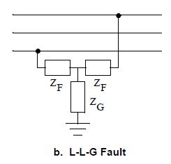
Hey guys, I am trying to simulate a L-L-G fault inside both PSSE and PSCAD however the information that I have found inside PSSE documents does not seem to achieve the same result inside PSSE. Inside the POM on page 685 (V32) or 9-14 for page numbers. This indicates that the unbalanced fault appears like so.

i.imgur.com/py2znVO.png

However when making a fault using the command below.

psspy.distscmufault([0, 1, 2, fault_bus], [23/(66^2/100), 0, 0, 0])

My understanding is that this would indicate a fault like below.

i.imgur.com/3Hjsm58.png

Please let me know if this is an incorrect assumption.

haveityourwa's avatar
25
haveityourwa
asked 2018-03-28 19:45:54 -0500
edit flag offensive 0 remove flag close merge delete

Comments

add a comment see more comments

1 Answer

0

Are you referring to this figure?

image description

I believe you have 46 ohm fault impedance between the phases and 0 ohm to ground at the mid-point.

perolofl's avatar
3.8k
perolofl
answered 2018-04-04 10:43:30 -0500, updated 2018-04-04 13:19:34 -0500
edit flag offensive 0 remove flag delete link

Comments

Thanks for the reply that is the image i am referring to and my assumption was the same that the fault impedance between the phases would be 46 ohms, however when trying to simulate the same fault inside PSCAD as above the resulting voltage drop was not equal.

haveityourwa's avatar haveityourwa (2018-04-04 19:40:51 -0500) edit
add a comment see more comments

Your Answer

Login/Signup to Answer