Ask Your Question
0

L-L-G Model Inside PSSE

asked 2018-03-28 19:45:54 -0500

haveityourwa gravatar image

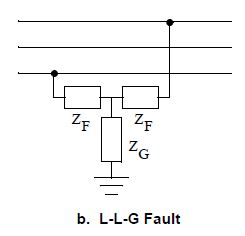
Hey guys, I am trying to simulate a L-L-G fault inside both PSSE and PSCAD however the information that I have found inside PSSE documents does not seem to achieve the same result inside PSSE. Inside the POM on page 685 (V32) or 9-14 for page numbers. This indicates that the unbalanced fault appears like so.

i.imgur.com/py2znVO.png

However when making a fault using the command below.

psspy.distscmufault([0, 1, 2, fault_bus], [23/(66^2/100), 0, 0, 0])

My understanding is that this would indicate a fault like below.

i.imgur.com/3Hjsm58.png

Please let me know if this is an incorrect assumption.

edit retag flag offensive close merge delete

1 answer

Sort by ยป oldest newest most voted
0

answered 2018-04-04 10:43:30 -0500

perolofl gravatar image

updated 2018-04-04 13:19:34 -0500

Are you referring to this figure?

image description

I believe you have 46 ohm fault impedance between the phases and 0 ohm to ground at the mid-point.

edit flag offensive delete link more

Comments

Thanks for the reply that is the image i am referring to and my assumption was the same that the fault impedance between the phases would be 46 ohms, however when trying to simulate the same fault inside PSCAD as above the resulting voltage drop was not equal.

haveityourwa gravatar imagehaveityourwa ( 2018-04-04 19:40:51 -0500 )edit

Your Answer

Please start posting anonymously - your entry will be published after you log in or create a new account.

Add Answer

[hide preview]

Question Tools

1 follower

Stats

Asked: 2018-03-28 19:45:54 -0500

Seen: 362 times

Last updated: Apr 04 '18