Revision history [back]
| | 1 | initial version |

In a network there will be currents flowing in the healthy phases at LG-faults, even if all loads and shunts are ignored.
At LG-fault the sequence currents are equal at the fault location, but the impedance and layout of the positive, negative and zero sequence systems are different.
So, normally there are currents in the healthy phases of the lines/transformers feeding the faulted bus.
| | 2 | No.2 Revision |
In a network there will be currents flowing in the healthy phases at LG-faults, even if all loads and shunts are ignored.
At LG-fault the sequence currents are equal at the fault location, but the impedance and layout of the positive, negative and zero sequence systems are different.
So, normally there are currents in the healthy phases of the lines/transformers feeding the faulted bus.
EDIT: An example with a simple non-loaded system with only reactances as shown below:
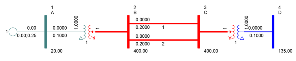
The Thevenin positive sequence reactance at bus 3 is 0.45 pu and the zero sequence reactance is 0.08 pu. The zero sequence reactance for the branches is 0.6 pu each, and the zero sequence reactance of each grounded transformer is 0.1 pu.
LG-fault at bus 3 gives the following results with ASCC:
AT BUS      3     [C           400.00] AREA    1  *** FAULTED BUS IS:      3     [C           400.00] ***   0 LEVELS AWAY ***
 PRE  FAULT (kV L-G)  VA:/230.94/30.00
 POST FAULT (kV L-G)  V+:/124.90/30.00  V-:/106.04/-150.00  V0:/18.85/-150.00  VA:/0.00/0.00  VB:/201.99/-68.05  VC:/201.99/128.05
 THEVENIN IMPEDANCE, X/R  (PU)  Z+:0.000000+j0.450000, 9999.999  Z-:0.000000+j0.450000, 9999.999  Z0:0.000000+j0.080000, 9999.999
                                                  X------------------------------------LINE TO GROUND (LG) FAULT-----------------------------------X
 X----------- FROM ------------X AREA CKT I/Z         /I+/   AN(I+)     /I-/   AN(I-)     /I0/   AN(I0)    /3I0/   AN(I0)   RE(Z0)   IM(Z0)  APP X/R
      2     [B           400.00]    1 1   AMP/PU      73.6   -60.00     73.6   -60.00     14.7   -60.00     44.2   -60.00 0.000000-0.200000 9999.999
      2     [B           400.00]    1 2   AMP/PU      73.6   -60.00     73.6   -60.00     14.7   -60.00     44.2   -60.00 0.000000-0.200000 9999.999
      4     [D           135.00]    1 1   AMP/PU       0.0     0.00      0.0     0.00    117.8   -60.00    353.5   -60.00 0.000000 0.000000  0.00000
 INITIAL SYM. S.C. CURRENT(I''k)(RMS)     AMP        147.3   -60.00    147.3   -60.00    147.3   -60.00    441.8   -60.00
                                                  --------------------------------------------------------------------------------------------------
 X----------- FROM ------------X AREA CKT I/Z         /IA/   AN(IA)     /IB/   AN(IB)     /IC/   AN(IC)                     RE(ZA)   IM(ZA)  APP X/R
      2     [B           400.00]    1 1   AMP/PU     162.0   -60.00     58.9   120.00     58.9   120.00                   -0.00000 0.236364 9999.999
      2     [B           400.00]    1 2   AMP/PU     162.0   -60.00     58.9   120.00     58.9   120.00                   -0.00000 0.236364 9999.999
      4     [D           135.00]    1 1   AMP/PU     117.8   -60.00    117.8   -60.00    117.8   -60.00                   -0.01540 0.108889  7.07254
 INITIAL SYM. S.C. CURRENT(I''k)(RMS)     AMP        441.8   -60.00      0.0     0.00      0.0     0.00
 ---------------------------------------------------------------------------------------------------------------------------------------------------
There is only fault current in phase A at bus 3 (441.8 A), but there is current flowing in phase B and C in the feeders from bus 2 and 4.
There is no positive and negative sequence current in the transformer 3-4 and the zero sequence current is 147.3 A. This leads to that the phase currents in that transformers is equal to 147.3 A in all phases!!!
This is according to the theory! At the faulted bus the sequence currents add up to 0 in phase B and C, but not in the individual feeders from bus 2 and 4.
| | 3 | No.3 Revision |
In a network there will be currents flowing in the healthy phases at LG-faults, even if all loads and shunts are ignored.
At LG-fault the sequence currents are equal at the fault location, but the impedance and layout of the positive, negative and zero sequence systems are different.
So, normally there are currents in the healthy phases of the lines/transformers feeding the faulted bus.
EDIT: An example with a simple non-loaded system with only reactances as shown below:
The Thevenin positive sequence reactance at bus 3 is 0.45 pu and the zero sequence reactance is 0.08 pu. The zero sequence reactance for the branches is 0.6 pu each, and the zero sequence reactance of each grounded transformer is 0.1 pu.
LG-fault at bus 3 gives the following results with ASCC:
AT BUS      3     [C           400.00] AREA    1  *** FAULTED BUS IS:      3     [C           400.00] ***   0 LEVELS AWAY ***
 PRE  FAULT (kV L-G)  VA:/230.94/30.00
 POST FAULT (kV L-G)  V+:/124.90/30.00  V-:/106.04/-150.00  V0:/18.85/-150.00  VA:/0.00/0.00  VB:/201.99/-68.05  VC:/201.99/128.05
 THEVENIN IMPEDANCE, X/R  (PU)  Z+:0.000000+j0.450000, 9999.999  Z-:0.000000+j0.450000, 9999.999  Z0:0.000000+j0.080000, 9999.999
                                                  X------------------------------------LINE TO GROUND (LG) FAULT-----------------------------------X
 X----------- FROM ------------X AREA CKT I/Z         /I+/   AN(I+)     /I-/   AN(I-)     /I0/   AN(I0)    /3I0/   AN(I0)   RE(Z0)   IM(Z0)  APP X/R
      2     [B           400.00]    1 1   AMP/PU      73.6   -60.00     73.6   -60.00     14.7   -60.00     44.2   -60.00 0.000000-0.200000 9999.999
      2     [B           400.00]    1 2   AMP/PU      73.6   -60.00     73.6   -60.00     14.7   -60.00     44.2   -60.00 0.000000-0.200000 9999.999
      4     [D           135.00]    1 1   AMP/PU       0.0     0.00      0.0     0.00    117.8   -60.00    353.5   -60.00 0.000000 0.000000  0.00000
 INITIAL SYM. S.C. CURRENT(I''k)(RMS)     AMP        147.3   -60.00    147.3   -60.00    147.3   -60.00    441.8   -60.00
                                                  --------------------------------------------------------------------------------------------------
 X----------- FROM ------------X AREA CKT I/Z         /IA/   AN(IA)     /IB/   AN(IB)     /IC/   AN(IC)                     RE(ZA)   IM(ZA)  APP X/R
      2     [B           400.00]    1 1   AMP/PU     162.0   -60.00     58.9   120.00     58.9   120.00                   -0.00000 0.236364 9999.999
      2     [B           400.00]    1 2   AMP/PU     162.0   -60.00     58.9   120.00     58.9   120.00                   -0.00000 0.236364 9999.999
      4     [D           135.00]    1 1   AMP/PU     117.8   -60.00    117.8   -60.00    117.8   -60.00                   -0.01540 0.108889  7.07254
 INITIAL SYM. S.C. CURRENT(I''k)(RMS)     AMP        441.8   -60.00      0.0     0.00      0.0     0.00
 ---------------------------------------------------------------------------------------------------------------------------------------------------
There is only fault current in phase A at bus 3 (441.8 A), but there is current flowing in phase B and C in the feeders from bus 2 and 4.
There is no positive and negative sequence current in the transformer 3-4 and the zero sequence current is 147.3 117.8 A. This leads to that the phase currents in that transformers is equal to 147.3 117.8 A in all phases!!!
This is according to the theory! At the faulted bus the sequence currents add up to 0 in phase B and C, but not in the individual feeders from bus 2 and 4.
