Ask Your Question
0

Model Writing in PSS/E

asked 2021-09-15 03:01:18 -0500

TSENG gravatar image

updated 2021-09-16 01:28:25 -0500

I have just started to learn PSSE model writing. I was looking chapter 23-Model Writing on POM 34.2 Manual, it is an Simple Excitation System, there is one part that I do not understand, what is the meaning between block diagram and code, can someone please tell me? Thank you for your help.

STATE(K)=ECOMP(I)
STATE(K+1)=EFD(I)
VREF(I)=ECOMP(I) + EFD(I)/CON(J+1)
edit retag flag offensive close merge delete

1 answer

Sort by ยป oldest newest most voted
0

answered 2021-09-16 10:30:54 -0500

perolofl gravatar image

The block diagram for DEMOEX model:

image description

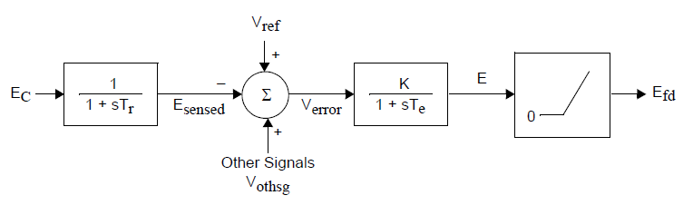
The first time constant block has steady state gain 1 and the second block has steady state gain K. The output of time constant blocks are the same as the state of the block. This means that Esensed = Ec and E = Efd at steady state (mode 1). The two states therefore becomes:

STATE(K) = ECOMP(I)
STATE(K+1) = EFD(I)

where ECOMP and EFD are the arrays with measured voltage and field voltage respectively. I is the index for the machine.

The relationship between input and output at steady state is:

(Vref-Ec+Vothsg)*K = Efd

Efd is known (calculated by generator model in mode 1). Ec is terminal voltage if no compensation model is used. Vothsg is zero at steady state. The formula is rewritten to get the necessary value of Vref at initialisation:

Vref = Ec + Efd/K

The initialisation is made backward from the output signal (Efd) and forward from the input signals in mode 1.

edit flag offensive delete link more

Comments

Thank you very much

TSENG gravatar imageTSENG ( 2021-09-17 02:10:40 -0500 )edit

Your Answer

Please start posting anonymously - your entry will be published after you log in or create a new account.

Add Answer

[hide preview]

Question Tools

1 follower

Stats

Asked: 2021-09-15 03:01:18 -0500

Seen: 650 times

Last updated: Sep 16 '21